DEDICATION

This blog is dedicated to the restoration of the Austin Healey 3000...among the most desirable of all British sports cars.

Saturday, June 30, 2012

THE ENGINE BEFORE AND AFTER

Restoring an engine and transmission is a greasy, rusty task.  The disassembly, cleaning, painting and reassembly is time consuming to say the least.  To the right is a photo of the engine and transmission during the disassembly process.


After the engine and transmission were rebuilt, the cleaning and painting process began.  
We painted them separately and then put them together.  Then the fasteners were painted the same color as the engine.  This was done because the engine and transmission assembly was painted after it was put together at the factory.  No bright, shinny bolts are visible here.


No fluids will be added to this drive assembly until it is installed in the car.  A priming tank will be used to charge the engine's oiling system.  A priming tank is a pressurized vessel that is filled with oil and connected to the engine.  When the pressure valve is opened oil is forced throughout the entire lubrication system before the engine ever turns over the first time.  Failure to do this will cause excessive wear to the bushings, bearings and rings.
Hopefully we will be installing the engine toward the end of next week.

Later,
Tom McCurry 

Friday, June 29, 2012

INSTALLING THE INTERIOR HEAT SHIELD

The left hand drive Austin Healey 3000s are notorious for keeping the driver warm...a bit too warm.  The exhaust system, you see, is located directly underneath the the driver's seat.  This makes the Big Healey driving experience somewhat less than pleasant, especially on a hot summer day.  
With Tim's permission, of course, we installed a special heat shield between the floor pan on the driver's side and exhaust system.  We are also applying another layer of the same material to the topside of the floor pans.
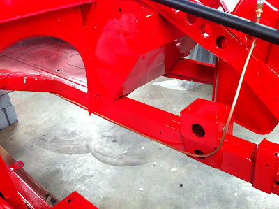
 In preparation for the heat shield installation, several coats of Colorado Red were applied to the cockpit.
 In the photos to the left and below you will see the heat shield that has been applied to the floor pans.
This "blanket" will reduce heat from the engine and noise from the road.  The car will sound and feel more "solid" and the best part is, no one will ever know it's there.  
When the installation of the blanket has been completed, there will be a barrier between the engine's exhaust system and the driver.  I'm not saying it will even remotely resemble air conditioning, but the driver will certainly be more comfortable.


I love this car...
Tom McCurry


Thursday, June 28, 2012

ANOTHER BEFORE AND AFTER


It's hard to believe this is the same car.  To the right is a photo of the engine compartment.  The brake line manifold and original brake lines are shown in the center of the photo.  You may have difficulty seeing the original shock absorber and steering idler because they are covered in oil, dirt and rust.
Not quite the same camera angle but the new brake lines and manifold are now installed.  In the upper left hand corner of the photo to the left you can see the new shock absorber and steering idler.
Quite a difference.


Stay tuned...
Tom McCurry

Wednesday, June 27, 2012

RESTORING THE FUEL TANK

The fuel tank was in good condition with only a few minor flaws.  Don removed the paint and prepared it for primer.  
The tank will be coated with epoxy primer.  The finish paint will be a single stage urethane.  The inside of the tank will be coated with a rust preventative sealer that is impervious to gasoline.


Later,
Tom McCurry

Tuesday, June 26, 2012

THE NEW EXHAUST SYSTEM

 Tim bought a state-of-the-art exhaust system...polished stainless steel.  It is absolutely flawless.  It was purchased from Moss Motors (mossmotors.com) for a very reasonable price.


 Shown to the left and below are the hanger assemblies for the new exhaust system.


Because of the attachment of the rotisserie to the frame of the car, the exhaust system cannot be installed until the car is on its wheels and the rotisserie is removed.


Stay tuned...
Tom McCurry


Monday, June 25, 2012

HYDRAULIC PIPING IN PLACE

I completed the installation of the brake and clutch piping today.  The process did not require a great deal of time.  Having the original lines to use as patterns makes the fabrication process so much easier.  So, if you ever have the need to replace the hydraulic system on your car, be sure to remove the old lines carefully.  Try not to bend them if at all possible.

 The photo to the left shows the installation of the clutch hydraulic line and flexible hose that connects the master cylinder to the clutch slave cylinder.
 A hydraulic line extends from the manifold, pictured above, to the rear manifold and flexible connecting hose, shown in the photo to the right.
The photo to the left shows the attachment of the hydraulic and fuel lines to the Healey's frame.  A work of art.


More to come...
Tom McCurry

Sunday, June 24, 2012

INSTALLING NEW BRAKE LINES

 After being out of town for several days,  I spent a few hours today in the shop installing the new front brake lines.  The manifold, shown in the photo to the right, is mounted on the wheel house just above the frame.  The brake lines serving all four wheels are connected to this manifold.  
 The photo to the left shows the installation of the brake line for the left side, or drivers side, of the car.  Notice the connection to the flexible hose serving the brake caliper.

 The photo to the right shows the installation of the right side brake line, flexible caliper hose and manifold.

This photo of the manifold shows the right and left brake line and master cylinder to manifold line connections.  The line that runs from the manifold to rear brakes is the only remaining connection.


Later,
Tom McCurry

Saturday, June 23, 2012

BEFORE AND AFTER

For those of you who may have forgotten the condition of this Healey on the day it rolled into our shop, let me take this opportunity to treat you to some before photos of the rear axle assembly.


 As we began to dismantle the drive train, we encountered more than our share of rusted fasteners and compromised parts, many of which required replacement.  These photos certainly bring back memories.


Now for the "after".  The entire assembly has been restored.

Quite stunning, wouldn't you agree?

Y'all come back now...
Tom McCurry

Friday, June 22, 2012

INSTALLING REAR BRAKE LINES

As I said in my last post, installing new hydraulic lines is much easier when you have the originals to use as a pattern.  The photo to the left shows the installation of the brass brake line manifold which distributes the fluid from the master cylinder to each of the rear wheels.  Looking closely, you will notice a flexible hose extending from the front of the car to the manifold.  This connection must be flexible because the differential is continually moving up and down and the brake line extending from the front of the car is stationary.
 Fitting the brake lines from the manifold to the wheel cylinders was not difficult at all.  The original brass clamps were used to fasten the new lines to the differential.
 Another view of the brake line installation.
A view of one of the brass retainer clamps that stabilizes the brake line to the differential.  Amazingly, the designers of this car actually specified a threaded sleeve welded to the differential to attach this clamp.


More to come...
Tom McCurry

Wednesday, June 20, 2012

INSTALLING FUEL LINES

It is so much easier to fabricate new fuel lines and hydraulic lines when you have the originals to use as a pattern...easier but not easy.  Fabricating the new lines with the "close" bends of the originals was a bit time consuming, but not impossible.  The photo to the right shows the new fuel line connections to the fuel pump.  The copper lines extend from the fuel tank to the fuel pump and from the pump to the engine.

The line connecting the fuel pump to the carburetors is shown in the photo to the left.  After bending the new line to conform to the original, fitting it to the original clips on the car's frame required only minor adjustments.
The hydraulic brake lines will be installed next.

Stay tuned,
Tom McCurry

Monday, June 18, 2012

CHROME WIRE WHEELS

Chrome wire wheels were actually made famous by Jaguar and was the signature of the Jaguar XKE.  Since then, they have enhanced the appearance of almost every British sports car that would accept them.  The Austin Healey 3000 is certainly no exception.  Tim has chosen chrome wires for his Healey.
When the Big Healeys were fitted with painted wire wheels, the rear brake drums were painted silver.  Because of the similar color of the wheels and drums, the wheels lacked definition, so we are trying to chose a color similar to the that of the front disc brake rotor.
The photo shown above is the new chrome wheel mounted on the front disc brake rotor.  The photo below shows the chrome wheel on the rear brake drum.
We are looking for a color for the rear brake drum similar to the color of the front brake system that will enhance the chrome wires. What do you think?  Did we nail it?

Post a comment...
Tom McCurry


Saturday, June 16, 2012

HUB AND BRAKE ROTOR INSTALLATION


 The front hubs are cleaned and painted.
 The new bearings and seals are installed in the hubs as shown in the photo to the left.
 Next, the new rotors are fitted to the hubs in preparation for installation on the front spindles.
The photo to the left shows a complete front spindle assembly.


Does this look good, or what?
Tom McCurry

Friday, June 15, 2012

INSTALLING THE STEERING ASSEMBLY

We had such a productive day.  Don and I completed the installation of the front spindles and steering linkage including the steering box and column.  After fitting the hub, spindle and rotor,  we positioned one of the new chrome wire wheels.  This inspired us all.  What a great look. 

 In the photo to the left, you will see the installation of the steering idler and all the connecting rods on the  right  side of the car.
The photo to the right shows the installation of the steering box and linkage on the left side of the car.  


Another view of the steering linkage on the left side. 
In order to align the steering mechanism properly, we mounted the original steering wheel.  Moving the steering wheel to the center of its travel allowed us to locate the steering linkage in close proximity to its proper position.  Now, only minor adjustments will be required for proper alignment.  


Next week we will be installing the fuel delivery system,  brake and clutch hydraulics and the exhaust system.  Fitting these systems while the chassis is mounted on the rotisserie is much more efficient.  When the aforementioned has been completed, the wheels will be mounted and the Healey will be removed from the rotisserie.

Are you excited ?
Tom McCurry

Thursday, June 14, 2012

INSTALLING THE REAR SWAY BAR

 The differential and related systems, installations, are now complete.  I connected the rear sway bar today.  The rear sway bar is connected to the frame and the differential to prevent lateral movement.  You can see the frame connection of the sway bar in the photo to the right.


The differential connection of the sway bar is shown in the photo to the left.  


 I also connected the steering idler today.  The steering arms on both front swivel axles, the steering box and idler are all connected by cross rods.  The idler, pictured on the right, is mounted on the right side of the car.


The mounting bracket for the steering box, pictured in the photo to the left, is mounted on the right side or driver's side of the car. 


Soon, the idler and steering box will be connected by the cross rods, completing the steering system.

Later,
Tom McCurry

Wednesday, June 13, 2012

INSTALLING THE HANDBRAKE LINKAGE


 The handbrake on the Healey is a bit more complicated than most. The assembly uses metal rods fastened to a swivel that connects both brake assemblies. After refinishing all the components, its assembly was not at all time consuming.  The linkage, shown in the photo to the right is cable operated from the cockpit and simultaneously moves the brake shoes on both rear wheels


The photo to the left shows the handbrake cable fastened to the sheet metal to prevent contact with moving parts.  Notice the grease fitting on the cable...good idea.  


By the end of the day, we had also installed the heater blower motor.  All the connectors were in good restorable condition so they were reused.  We do this whenever possible.


We will be installing the new hydraulic brake and clutch lines in the next several days.  Both require some fabrication.

Stay tuned,
Tom McCurry
Tuesday, June 12, 2012

INSTALLING THE FUEL DELIVERY SYSTEM

 There are very few components of the fuel delivery system for this car.  The fuel tank, electric fuel pump and carburetors are all in remarkable condition.  The SU fuel pump is mounted on the side wall of the differential tunnel as shown in the photo to the right.

A close-up of the fuel pump and mounting bracket is shown in the photo to the left. 
The fuel tank will not be mounted until the trunk detailing is complete.  New fuel lines have been purchased with one exception.  For some reason, all the lines were available except for the line that runs from the fuel tank to the fuel pump.  Fortunately the line is in good restorable condition.  I spent an hour or so restoring this line.  It looks better than I expected.  It will be mounted tomorrow and you will be so impressed... LOL


Y'all come back now...
Tom McCurry


Monday, June 11, 2012

REAR WHEELS FITTED


Don and I spent the day installing the rear hubs, axles, brake drums and wheels.  We installed the reconditioned hubs and prepared them to receive the axles.


 The axles simply slide into position with only one phillips screw, shown in the photo to the right, holding it in place.  
 Next the brake drums are attached to the hub assembly.  They are held in place with two phillips screws.


After the brake drums are fitted, the wire wheel hub is attached with five locking nuts torqued to 60 foot pounds.
Now the original wheel, with a 41 year old Michelin tire in perfect condition, is fitted in place.  The finishing touch is the new chrome knock-off.  
Actually, the plan is to fit the car with new chrome wire wheels which will look great.  I just wanted to see a wheel on this car...it has been a while.
Just imagine, in the photo to the left, the brake drum painted silver.  The wire wheel, being the same color, would lose it's definition.  Originally, the drums were silver.  Black, as shown in the photo to the left, would certainly define the wheels better, but it would not be a duplication of original.  What do you think?

As soon as we have this car rolling, Tim is going to "take it around the block"...I'm going to push.

Later,
Tom McCurry